Soleil Royale
I’ve been pretty quiet lately for a number of reasons, mainly working on other projects.
A long time hobby of mine is building wooden ship models—I’ve always enjoyed it and found it relaxing, and over the years have tackled increasingly challenging ships. Here are some of my earlier projects:


The last two ships I built were the English ship Victory, which was Nelson’s flagship at the battle of Trafalgar and the San Felipe, which was the flagship of the Spanish Armada.

My next scheduled project was the Soleil Royale, which was the flagship of Louis XIV, the Sun King.
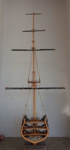
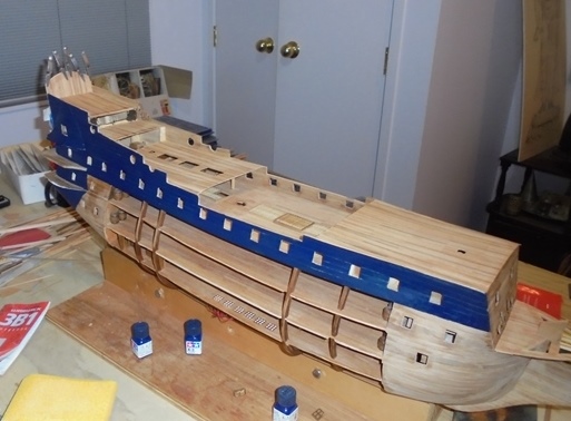
Although the Soleil Royale would present a challenge in terms of complexity, it wasn’t going to be substantively different than the previous two big ships. I wanted to do something a little different. Of all of the ship models I’ve built, the one that seems to interest most people is the cross section of the USS Constitution.
As a result, I decided to try to build the Soleil Royale with no sides to show the interior works. Normally it takes me three to five years to do a model. I started the Soleil Royale eleven years ago. The biggest issue was finding time. The same year I started the project, we also started CUE Haven, and also in that time I published my two novels. So the ship wasn’t always getting priority.
The idea immediately presented huge challenges and required a lot of research and planning. No one knows how the ship actually looked inside—it was destroyed in 1692. Also, I wasn’t sure how to construct a ship model without the basic structural support that a kit normally provides.
To figure out the internal layout, I did considerable research on how ships of the period in general and French ships in particular were laid out and found a number of generic side view diagrams showing the layout of the decks of old ships.
I was fortunate to find a book in the Auckland Library about the restoration of the HMS Victory after it was damaged by bombs during WWII. The original ship is still preserved at Portsmouth and the Victory was originally built about 100 years after the Soleil Royale so allowing for technological changes over that period of time and known differences between English and French ships, I could use the Victory as an idea of what the Soleil Royale looked like inside. Accompanying the book is a box containing 17 (huge) sheets of plans. There is one for each deck and it was exactly what I needed.


Using the plans in the book I was able to draw detailed plans to scale based on the actual dimensions of the model.

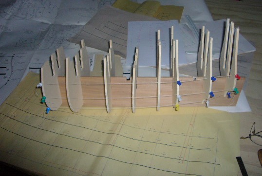
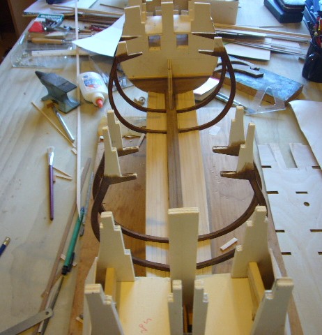
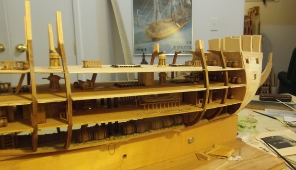
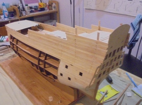
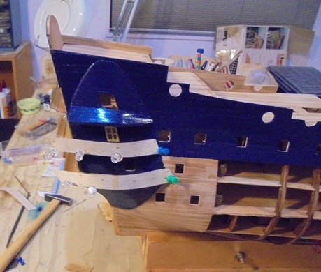
Normally when you build a wooden ship model, you build a minimalist skeleton out of plywood that no one will ever see. That is then covered with two layers of wood planks. You do not build the interior decks, because they will never be seen. The platform for the guns on the lower decks has no relationship to an actual deck. To get an idea of the issue, here is the interior structure of the San Felipe:

The vertical white frames would not exist on a real ship—they would be ribs like whale bones and there would have been many more of them. The white horizontal platforms with little blocks are simply place holders for positioning of the guns. When the ship is finished, you only see the barrels sticking out. The kit provides thin plywood sheets in the form of the top decks (which are visible in the picture). They are precut to fit into the framework and you just cut little fine wood planks and cover up the plywood to make it look like a deck.
For the Soleil Royale with no sides, I could use none of this structure. I needed to decide how to build the decks, how to space them and support them and also figure out what was on each deck.
I built up a partial structure using the plywood frames provided in the kit and transferred my deck dimensions to the model:
Once I got the frames and strings aligned properly I marked the deck positions on the frames and calculated the size and shape of each of the decks.

The next task was to draw the details of each deck. I did this using the Victory plans and modifying them for scale and also for features that I knew the Soleil Royale would not have. For example, the Victory had a very modern pumping system and stove that would not have been present on the Soleil Royale.
I can hear purists complaining that my model is a fraud because there is no way I can prove that it is an exact replica of the original ship. In fact, it’s probably easier to prove that it isn’t exact. But my objective was never to create a true and accurate replica, but I tried to be as accurate as possible based on available data and ship building research.
It was now time to make some difficult decisions about construction. My two big concerns as I made these decisions were how to (1) prevent warping and (2) ensure the decks were supported and didn’t sag.
When building one of these models you are constantly turning them and pounding and filing and sanding. So I needed to come up with a design that would be strong and with two thirds of the hull planks removed and with no interior framework, I was concerned that there may be stresses that would distort the structure either during or after building.
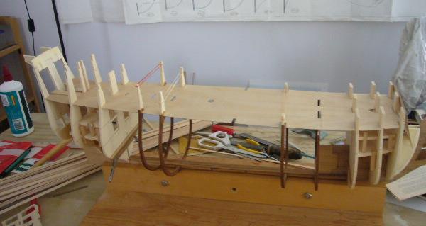
That led me to decide to use the frames supplied with the kit. I decided to cut them to make them look like the ribs that the actual ship would have. They would provide the needed support to build the walls and would also solve the problem of how to support the decks because I could attach the decks to them as I worked up.
I cut the frames from the plywood pieces supplied with the kit, and planked them with walnut to hide the plywood appearance. I also had to cut out a section of the false keel that is provided by the kit because it would block the view through the hold.

I then stained the plywood sections because they will be exposed.

Lastly, I attached them to the keel to form the outline of the ship:

Securing the ribs and positioning them properly was a huge challenge and took a few tries. When I finally got them where I wanted them I decided that I had too many and took out the two in the center to open up more of the decks.
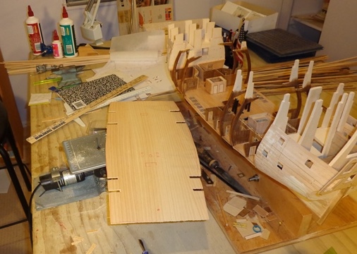
I then made a template of the lowest deck above the hold (the orlop deck) to make sure that I would be able to fit in the decks with the ribs in place and also to gauge how best to support the decks when in place. All of this helped to confirm my measurements and deck layout organization.
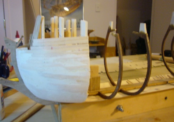
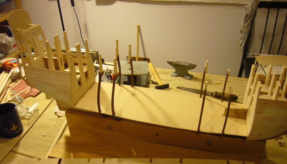
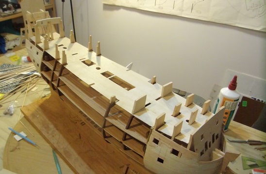
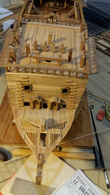
The next step was to proceed to build the bow and stern of the ship according to the original plans because they weren’t affected by the interior work I was doing. I put in the false decks and cannon blocks for the gun ports that would be planked, fitted the bow and stern structures and did the first layer of planking in the areas that would be covered.

The next challenge was to determine how to build the hold.
I planked the bottom of the ship and that would determine the amount of hold floor I would have to work with.

I needed to figure out where the mast steps would be located and then had to allocate the available space to create a reasonable replica of how the hold in the exposed areas would look. I discovered that the first thing I needed to do was find out how the orlop deck, the first deck above the hold, was laid out. This was important because structures on the orlop deck, especially the hanging magazines, would impact the layout of the hold. There are also steps and ladders between the decks and I needed to know where to put them.
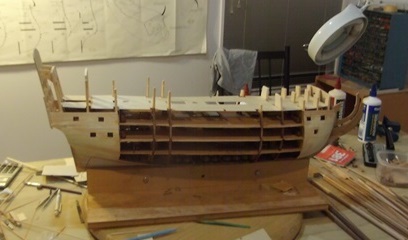
At that point I cut out the orlop deck based on the plans I had drawn earlier. I cut each deck out of a sheet of plywood, cut out the openings and planked over the plywood to create the appearance of decking. To prevent warping I did run beams between the frames.

I then determined where the masts and other structures would be located and cut holes in the ply.

Once I was happy with the positioning of the deck, I started to put in some of the hold fittings and fixtures. I knew I’d need a lot of barrels and sourced various sizes of barrels and prepared them by painting the hoops and varnishing them.

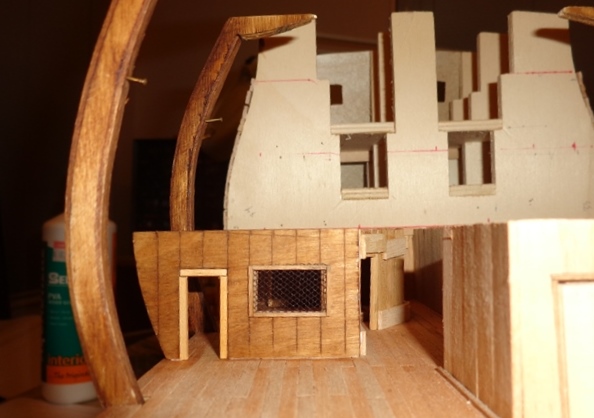
I built some walls between the two most fore and aft strakes and used aquarium gravel to simulate ballast.

I kept a part of the false keel to provide additional structural support and then needed to make a number of decisions about how to use the space. I cut doorways wherever I could to reflect that the crew would have had to move through these various areas. I thought the layout made for interesting opportunities to put in additional details.


I installed the orlop deck, planked it and installed some of the fittings.


As I thought about building the rooms and structures on the orlop deck, I decided that I would try to finish off each deck as much as possible before moving up. That meant going back to the hold and adding some additional detail.


It was at that point that I realized that it was going to be too dark to see much of the detail I was building. I researched model lighting and found a company that supplies tiny LEDs and lots of good advice on how to install them. I settled on the smallest yellow LEDs they provided thinking that they might simulate lantern light.


I really liked the look but now I had the challenge of how to retrofit the lighting in the hold and also to wire the rooms on the orlop deck.
I went ahead and planned the layout of the orlop deck and built the rooms and hallways.


I had decided that I would put the power supply for the lights in the base of the ship and run the wires up through the bottom of the ship. I could attach the wires to the ceiling of the hold. To get the lights to the ceiling of the orlop deck, I hollowed out one of the dowels that represent the pump pipes and ran the wires up through the pipe.

I could then fit the gun deck (ceiling of the orlop) and get an idea of where to put in the orlop lights.


Before continuing I added some of the features to the various rooms on the deck.


I then ran the wiring for the lights to the various rooms.

I then cut out the gun deck and fitted it in place, making sure that the mast alignment was still correct.

Then came one of the first major moments of truth—a test of the lights to see how they looked.


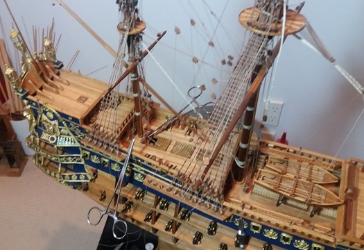
The next step was to tackle the gun decks. These would be less challenging from a technical perspective because they have much less detail, but I needed to develop logical access paths between the decks and decide how much detail to include. On a real ship, the guns would have had a lot of complicated tackle to secure them to the sides of the ship. But since this ship has no sides, there was no practical way to do all the work.
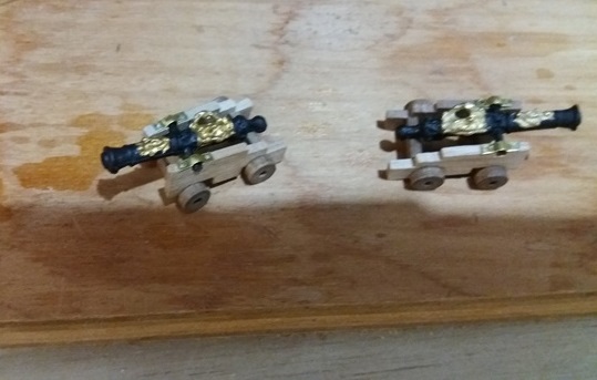
The kit I was building provided guns that are mounted in blocks inside the ship, so all you see is the ends sticking out of the gunports. They have a peg on the end to mount them in holes in the blocks. I decided to paint them to simulate the iron colour and to highlight the decorations.

I sourced some gun carriages, cut off the end of the pegs and rounded them to simulate the ball at the end of each gun and mounted them.
I built all of the guns and figured out where to place them but decided that attaching them in place would be one of the last things I’d do so they wouldn’t get in the way.
The next task was to plank the gun deck.

And then installed railings around the companionways, grates and shot garlands, capstans and the pump.

It was important to make sure that the pump pipes lined up with the pump.

I then installed and planked the middle gun deck.


I also built the bulkheads at each end of the gun deck in order to conceal the structural framework supporting the bow and stern.

I then added in the detail on the middle gun deck.
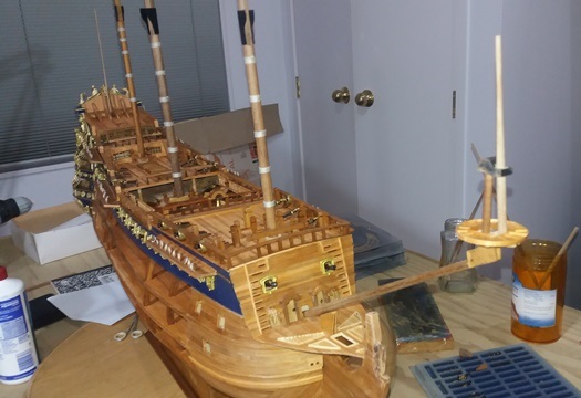
I could now breathe a sigh of relief because technically, from now on, I would be building the ship according to the plans provided with the kit. All of the upper works and finishing touches were based on the original kit design.
The first step was to install the upper deck which had been provided in the kit. I’d used the side frames which had supports for the deck and the upper bulwarks.
And for the first time I could get an idea of how the finished ship might look!
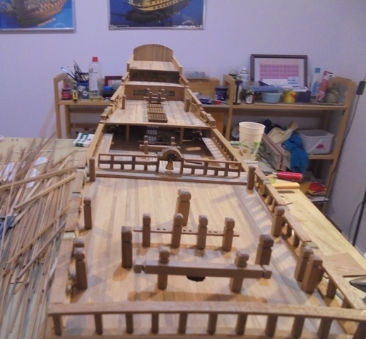
I planked the upper deck and installed grates, and then installed the quarter deck, fo’c’sle and poop decks.

And built up the bulwarks.

Then came the interesting challenge of cutting out the upper deck gunports.

The top decks were planked:

And it was time to put on the second layer of planking.

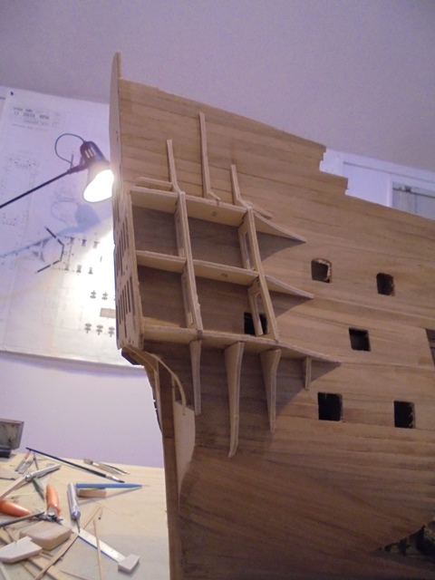
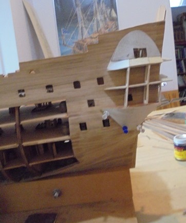
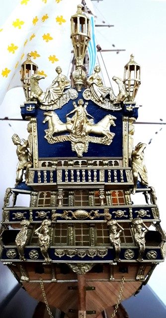
Next came a series of interesting challenges. The stern of the Soleiel Royale has big wraparound galleries and also an unusual raised area under the side galleries. The kit provides precut pieces to help build the structure.
The raised area supports some very interesting decorative work and it took some effort to make sure that the structure I was building would match up with the work.

Once everything looked right it was time to build the raised section. The kit simply advises laying thin wood planks over the frame to build up the area but I thought that would never look quite right, so I built the structures out of the thinnest plywood I could find. That would ensure that the ends were all straight and there would be no gaps.
I installed the thin planks on top of the plywood and planked the roof and floors of the galleries after painting the area that would be hard to access later.
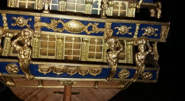
It was then time for another deep breath. This time to paint the bulwark and gallery areas. The kit suggests a light blue, but for the Royal Sun, I decided to use ‘royal blue.’ The point of the paint is to help the gold decorative work show up so a darker colour made more sense. I masked off the area and went to work.

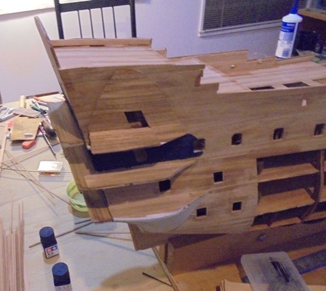
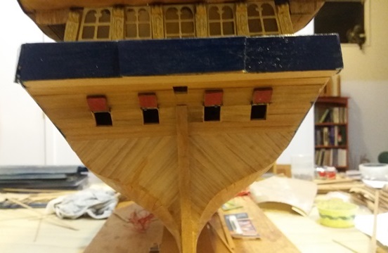
Now was the time to tackle the stern. The first step was planking.

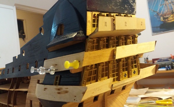
The stern of the ship has three levels of windows and doors and as usual, the kit provided stamped metal sheets.
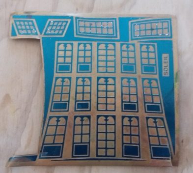
The idea is that you cut paint the windows blue or gray to look like glass reflecting sky and water and when you rub off the excess you are left with a brass outline. That usually isn’t a bad look although it’s hardly realistic. Because the stern of the ship is so ornate and because I was installing lights, I wanted something different.
Cutting out the little windows was out of the question but I found a local company who does laser cutting. I gave them a thin square of plywood and an outline of the windows on the sheet and they cut them out beautifully. I then used thin yellow plastic to simulate the horn that the windows would have been made of at that time.
I’m really happy with the result:
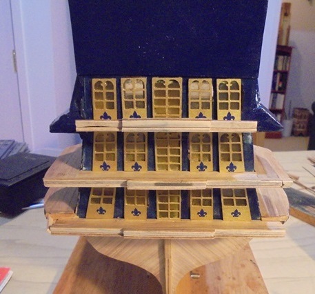
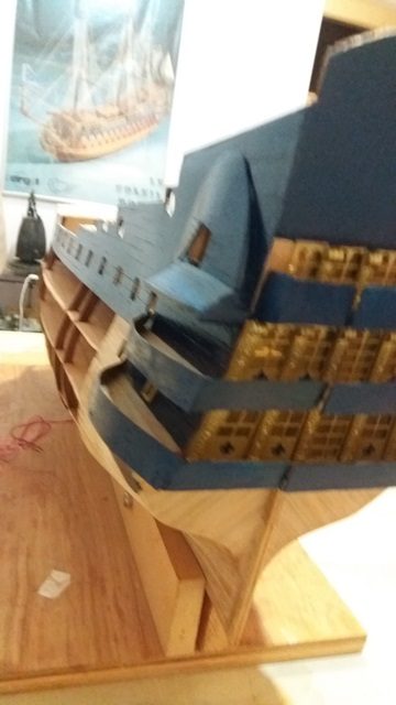
In order to dress things up a bit I added the blue fleur de lis to each window. I found them on a web site selling stick on fingernail decorations!
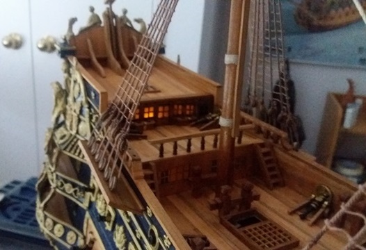
Here is a view from the main deck:

And with the lights on:

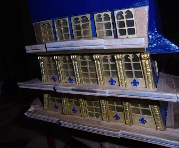
And this is after I added some of the brass decorations:


The next step was to install the solid railings around the galleries.
After making sure everything fit and was at the right angle I painted the railings.

Before installing the brass decorations, I decided to do the work on the decks, starting with the railings.


And the access doors under the fo’c’sle:

And the various bits and fife rails:

According to the plans, there are no railings on the walkways connecting the quarter deck and the fo’c’sle, but I thought they would look good (and the sailors would appreciate them).


And then finished off the bow work.
The next task was one of the biggest challenges—building the boats. This time I took a long look at the materials supplied in the kit and decided that they needed to be re-engineered in order for the boats to look at all decent. I repositioned all of the ribs to make the curves more realistic.


It was time to finish off the stern and install the gun port lids.
I got some gold stick on fleur de lis and added them for additional decoration.

I added a few more pillars and other details to the gun decks.


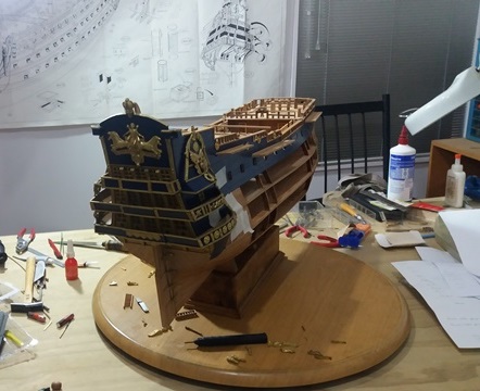
It was now time to tackle another challenging task—the stand for the ship. Usually the stand is a fairly straightforward project but this time I had the additional challenges of concealing the power supply for the lights and also providing additional height so that it would be easier to see the lower decks where most of the detail is.
I drew up a few designs involving drawers and sliding doors but my good friend Alan suggested more straightforward solid block approach. He generously provided the block and even drilled the massive hole for the batteries and switch.


The wiring exits the bottom of the ship and threads through the middle support bracket. The batteries and switch are accessed through the round door.

There was another breathless moment as the lighting was tested to make sure all the connections had survived.

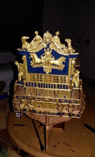
With the ship securely mounted, it was time to attach the decorative brass. I had previously sanded off any rough spots or imperfections and painted each piece with gold enamel.

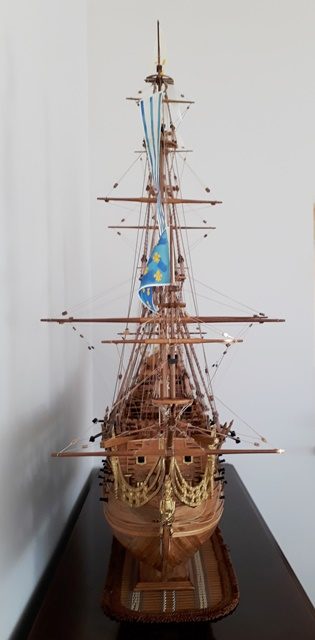
With the decorative work finished, I was in the home stretch with the masts and rigging being the last big tasks.


Lower shrouds rattled and the lights on!
I needed a short break after all the knots I tied for the shrouds and decided to go ahead and install the guns.


I didn’t mention it before, but an unusual quirk of the kit was that the plans didn’t have any way to access the poop deck. Usually, there would be ladders coming up from lower decks, but on this ship there is no logical place to put them because of the bulkhead doors under the poop deck. I took the liberty of installing a trap door that the crew may have used.

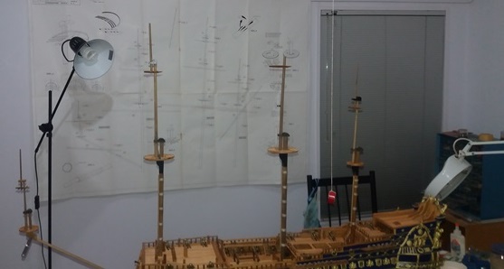
I then carried on with the rest of the rigging. In addition to topgallant masts, this ship also has royals and the masts were so tall I couldn’t safely reach them with the ship on my usual work table. As a result if moved to another room with a low table to support the ship.
As usual, the running rigging required a lot of bending and reaching and looked like a mess until it all got sorted out and tightened.


The final rigging job went relatively fast and after almost 11 years, the Soleil Royale was finished!


I hope you enjoyed the history of the model as much as I enjoyed building it.


Just brilliant Tom..you must have the patience of an Angel..well done..
Thanks Doug–looking forward to having you out to see the real thing!
Wow. I do not have words to describe how impressive that is!
Thanks!
This is incredible, so detailed and realisitc!
Thanks Niki, I appreciate your feedback.
No wonder you have been absent from the blogosphere Tom. What an amazing fete and how fantastic that it is now finished and you can display it. Where do you display these works of art?
And thank you. I have discovered CUE Haven. No doubt that is your brainchild. More congratulations from me.
And more thanks to whichever friend of yours in the US introduced me to you and your books.
Hi Judith–Thanks so much! I’ve built 8 ships and they are all on display in various places at home–makes dusting a real pain!
And thank you for checking out CUE Haven. It’s take a lot of time and energy but the forest is really starting to look good and we’ve met such amazing people. It’s been a joint project of my wife and I but we are trying to get more of the community involved to manage it into the future.
Yes, I can’t remember how our paths crossed, but I’m so glad we’ve been able to share thoughts and ideas. Keep safe!
Congrats Tom. Glad to hear you have continued with your hobby; Very Impressive!
Those are totally awesome!!!
Fantastic. Detail, accuracy and I would love to have a trip on one of those machines in real life.
Con Kiernan